ROBOAT
 |
This project aims at testing
the feasibility of driving an object using a GPS and
a digital compass.
In this case the object is a model boat that can
sail autonomously along a course planned in advance.
This explains the meaning of "Roboat" that
is the short form for "robot boat".
The project was built in order to take part in the
"Design99
Contest", organized by the magazine "Circuit
Cellar"
For this purpose the project had to be developed
using the new microcontroller "MC68HC908GP20"
produced by Motorola.
ROBOAT eventually won a first prize in the contest
(see
link).
|
Main components
The core is the controller M68HC908GP20
(the quad flat plastic pack version) that stores the coordinates
of the waypoints to follow and according to the data received
from the GPS and from the digital compass, controls the electric
motor for the propeller and the proportional servo for the rudder.
Three switches enable the test modes (disabling the control of
GPS and/or compass), and a potentiometer allows to trim the
rudder center position.
A MON08 interface provides a connection with the ICS08GP20
board, in order to control "Roboat" directly from a PC
for testing purpose and when new waypoints coordinates need to be
stored.
A 12 Volts lead battery supplies power to the devices. The
electric motor of the propeller is driven by 12 Volts directly,
while the other circuits receive 5 Volts power supply through
suitable regulators.
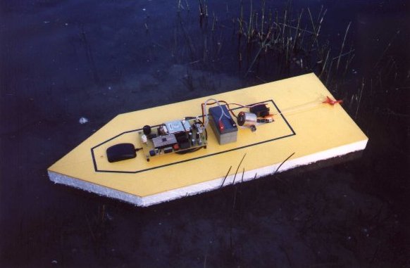
Mechanical
assembly
The structure of "Roboat" is very
simple, so that it can be easily modified and adapted, therefore
it is basically made of a sheet of polystyrene foam, 4 cm thick,
cut in the shape of a boat, and a thin sheet of plastic on
top that actually mounts all the devices: battery, electronics,
electric motor, propeller, servo and rudder.
While sailing, all the device are covered with a case that
protects them from water sprinklings.

Project test and
test area
Due to the small size and to the reduced capacity of the
battery, a typical journey of "Roboat" is only a few
kilometers long and needs to be done on a quiet and delimited
area such as a lake.
The area chosen for the first test of "Roboat" was the
lake "Idroscalo", close to Linate airport, 5 kilometers
east of Milan, in northern Italy.
It is an artificial lake, once used for landing and take-off of
seaplanes. Its dimensions are roughly 2.5 km by 100-200 m,
elongate in direction North-South. Nowadays it is used mainly by
oar- and sailing boats, therefore it is very quiet and safe for
the purpose of the test.
The journey chosen for the test is about 1.5 km long and it is
described by 4 waypoints, with their corresponding coordinates.
GPS
GPS means "Global Positioning System". It refers to
a modern technology that allows to immediately obtain the
coordinates of a site on the earth surface. The system is based
on a network of satellites that continuously transmit coded
signals around the globe. A GPS device receives these signals,
computes the position of the satellites and through a
triangulation computes its own position over the earth surface.
The accuracy of this method for the basic, commercial GPSs, is
said to be within 100 m for the 99% of the measurements collected
in the same place during a sufficient interval of time. Therefore
a course properly planned for "Roboat" should never
approach any obstacle (an island or a shoreline) at a distance
closer than 100 m.
The GPS device used in the projects is a Garmin mod. GPS25-LVS, with
the preamplified antenna GA27A.
Through the serial output it sends the following string of ASCII
data, according to the NMEA format, once every second, at a rate
of 4800 bps:
0 1
2 3
4 5
6
0123456789012345678901234567890123456789012345678901234567890123456789
======================================================================
$GPRMC,145055,V,4453.6083,N,00944.9533,E,000.0,000.0,070399,000.3,E*7F
The individual elements of this string are:
GPRMC NMEA
sentence type
145055 GPS time of
position fix (seconds)
V
data quality: A = valid position, V = receiver warning
4453.6083 latitude "ddMM.mmnn"
N
latitude N or S hemisphere
00944.9533 longitude "DddMM.mmnn"
E
longitude E or W hemisphere
000.0 speed over
ground (knots)
000.0 course over
ground (0-359.9 degrees)
070399 date of position
fix "ddmmyy"
000.3 magnetic
variation direction
E
magnetic variation E or W
7F
checksum byte (= byte1 eor byte2 eor byte3 eor … byte66)
The string is terminated by the ASCII codes "13" (carriage
return) and "10" (line feed).
Digital Compass.
To determine the direction Roboat is heading to (azimuth), it
uses a Digital Compass Sensor Analog mod. 6100, distributed by PEWATRON.
This sensor has the shape of a small cylinder 15 mm high and 13
mm in diameter, and contains a tiny magnet and two Hall-effect
sensors.
The magnet is free to rotate around its vertical axis and point
towards north under the influence of the earth magnetic field.
The two Hall-effect sensors are mounted around the tiny magnet,
90° apart each other. When the magnet rotates the outputs of the
two sensors describe a couple of sine and cosine curves that,
using a power supply of 5 volts, have an average value of 2.5
volts and swing between 2.8 and 3.2 volts.
The Roboat azimuth can then be computed as the ArcTangent of the
ratio between the displacements of the two curves from the
average.
Proportional Servo
The rudder is controlled by a Proportional Servo by Futaba.
The servo wheel turns in a range of +/-90° from its central
position, under control of a periodic positive pulse and the
amount of rotation of the wheel is proportional to the pulse
width.
The pulse is generated at pin_4 of Port_D, under control of Timer_1
which is set in PWM (Pulse Width Modulation) mode.
| Rudder position | Servo wheel rotation | Pulse width (msec) | value in Timer 1 |
| full left | -90° | 0.2 | $0200 |
| center | central position | 1.25 | $0C00 |
| full right | +90° | 2.3 | $1600 |
Electronic
Circuit description.
The electronic circuit receives power from the 12 volts
battery through the main switch SW1.
When SW1 is on, the green led D1 lights up to show that power is
available.
12 volts are applied directly to the electric motor under
control of IC4-PTC2, through the buffer IC3f and the
electronic switch TR1. C11 helps reducing the noise generated by
the motor when in use.
The rest of the circuit is powered with 5 volts through the
voltage regulators IC1-C2 and IC2-C3.
The reason for using two identical regulators is to insulate the
servo, so that the noise spikes that it generates are not passed
to the rest of the circuit.
Therefore IC2 powers the servo only and IC1 powers the rest.
IC4 is the core of the circuit. It is the micro-controller M68HC908GP20
and works with a frequency of 4.9152 MHz generated by the
oscillator X1, IC3a, R3, C7, C8.
C4 and C5 are mounted very close to the power supply pins VDD and
VDDA, to prevent noise problems.
A stronger filter for the pin VDDAD is provided by R4 and C6, in
order to prevent noise that might affect the AD conversion.
SW2 and C7 provide the manual reset to IC4.
The pins IRQ, RST, PTA0,7, and PTC0,1,3 of IC4 are connected
to the MON08 connector that provides a link, via a 16 ways flat
cable, with the ICS08GP20 board, in order to control "Roboat"
directly from a PC for testing purpose and when new waypoints
coordinates are to be loaded.
When the link is not in use (i.e. when "Roboat" is
sailing autonomously) a suitable socket is to be fitted to the
connector instead of the flat cable
IC4-PTD4 pin generates the PWM signal that controls the servo.
It is connected to the control input of the servo through the
buffer IC3b.
IC4-PTE1 pin receives the serial signal from the GPS after it
has been inverted by IC3d.
IC4-PTC4 pin controls the GPS power down mode through the buffer
IC3e.
IC4-PTD6 controls the red LED D2 through the buffer IC3c and lets
it flash every time the GPS receives a valid position.
The digital compass analog outputs as well as R8 (the trimmer
for centering the rudder) are connected to the AD converter
inputs of IC4 (pins AD0, AD1, AD2), through the low pass filters
R5-C10, R6-C11, R7-C12.
Here is the schematics of the electronic circuit:
Here are displays of the PCB layout:
Parts List:
Resistors:
· R1 560 W
· R2 100 W
· R3 1 MW
· R4 1 KW
· R5-7 10 KW
· R8 10 KW potentiometer
· R9 1 KW
Capacitors:
· C1-3 500 uF electrolytic
· C4-5 100 nF
· C6 1 uF electrolytic
· C7-8 18 pF
· C9 1 uF electrolytic
· C10-11 10 nF
· C11 22 nF
Semiconductors:
· D1 LED diode green
· D2 LED diode red
· TR1 TIP122
· IC1-2 LM7805 & heatsink
· IC3 HC4049
· IC4 MC68HC908GP20CFB
Switches:
· SW1 PCB mounting vertical type (SPDT)
· SW2-3 PCB mounting push type (SPST)
· SW4-5 PCB mounting slide type (SPDT)
Other:
· X1 - crystal 4.9152 MHz
· GPS - Garmin
mod. GPS25-LVS & antenna mod. GA27A
· COMPASS SENSOR ANALOG - PEWATRON mod.
6100
· PROPORTIONAL SERVO - FUTABA mod. FP-S148
· ELECTRIC MOTOR - brushed 12 V d.c.
· BATTERY - sealed lead-acid, 12 V, 1.2 AH
Connectors and sockets:
· K1 (battery) PCB mounted screw terminals, 2 ways
· K2 (motor) PCB mounted screw terminals, 2 ways
· K3 (servo) single row PCB headers, 3 ways, right angle
· K4 (GPS) double row PCB headers, 10 ways, straight
· COMPASS two s.i.l. sockets, 3 ways
· MON08 double row PCB headers, 16 ways, straight
· MON08 double row PCB socket, 16 ways
· IC3 d.i.l. socket, 16 ways
· IC4 two single row PCB headers, 22 ways each, straight
· IC4 two single row PCB sockets, 22 ways each
Software
The software is written in assembler for the M68HC908GP20 and
controls all the functions of "Roboat". The main
actions are:
· start the propeller and power up GPS
· acquire data from GPS
· compute Roboat present position
· compute the course needed to reach the next waypoint
· acquire data from the Digital Compass
· compute Roboat present course
· compute course correction in order to head towards the next
waypoint
· apply course correction to the rudder
· when the waypoint is close enough, select the next one and
head towards it
· when the last waypoint is reached, stop the propeller, power
down the GPS and stop the micro-controller
Because of all the computations with coordinates, big effort
was put in developing routines in assembler to deal with
simplified mathematics, in order to handle arithmetic operation
with four bytes numbers, azimuth angles and the trigonometric
function ArcTangent.
Download
ASM file
Email: riccardo.rocca@hotmail.com
Back to Home Page